


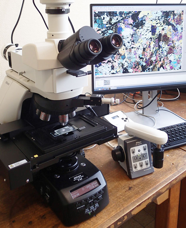
Automated microscopy
Nikon Ni-E
allowing the acquisition of :
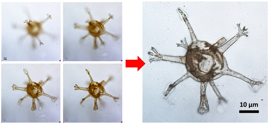
- multiplane images showing the structure of fossils in 3 dimensions:
The microscope automatically acquires a series of photos at different sample heights (focal distances), e.g. the 4 pictures of the left below. For a 3D object, only the zones that occur in the focal plane ("in focus") appear sharply while the rest is fuzzy. A software removes the fuzzy parts of each image and combines the sharp zones of each image taken at each focal plane. Thus can we build, from a series of photos that are sharp only locally, a "project" called "multiplane image" where the object is sharp in its entirety (image on the right below). The example below was acquired of a fossil microorganism extracted by Pr Thijs Vandenbroucke.
This imaging method is essential for a complete description of the morphology of a microfossil. The lateral resolution of optical microscopy in white light is ~0.5 micrometer. This microscope uses plain/polarized transmitted light, and/or reflected light (+/- DIC: differential interference contrast); these two techniques respectively produce projection views (transmitted light) and surface topography profiles (reflected light).
- centimeter scale mosaics detailling microscopic structure over the full size of macroscopic objects (up to 4 centimeters wide)
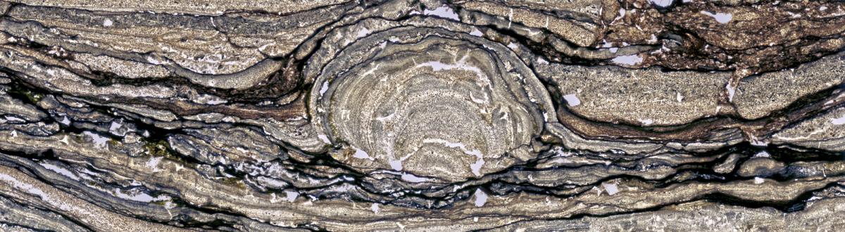
The mosaics are produced from hundreds to thousands of images (acquired by automated sample translation) stitched together with a software. The example below displays the mosaic of a thin section of rock (height ~ 1 cm). Such an image (here compressed) has a high resolution (2 Go or more) : this allows to zoom from the centimetre to the micrometric scale with a single file and to correlate the global structure of the object to microscopic observations.
These mosaics moreover allow to quantify phases / minerals / shapes / structures in a rock. With specific software, one can analyse the proportion of calcium carbonate (white and light brown on this images), and zones with clay minerals (dark brown). We can see on this image that the carbonate layers, in the to-right corner, have been eroded (by wave action or sediment injection) and covered by clayey sediments including solid fragments of carbonate layers.
- to localize X-Y-Z coordinates of microscopic fossils in rocks,
The software can locate micrometric zones (e.g. the microfossil shown above) in the global mosaic picture of a centimetre-scale object as a thin section or palynological preparation. The automated microscope can re-locate automatically the annotated zone of interest. The coordinates can be recorded and used to locate regions of interest for microscale molecular analyses such as ToF-SIMS or microscale extraction of ultrathin section with Focused Ion Beam.
Instrument funded by Région Hauts-de-France and the ANR.
Contact : Sandra Ventalon